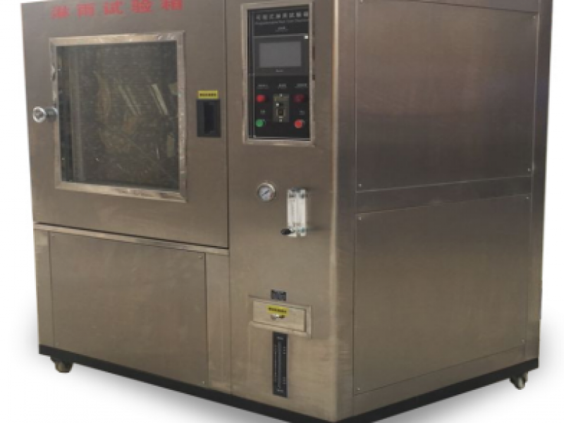
YS751‑IV Series Constant Temperature and Humidity Test Chamber (High‑End Export Model)
Scope of Application
【Operating Instructions】
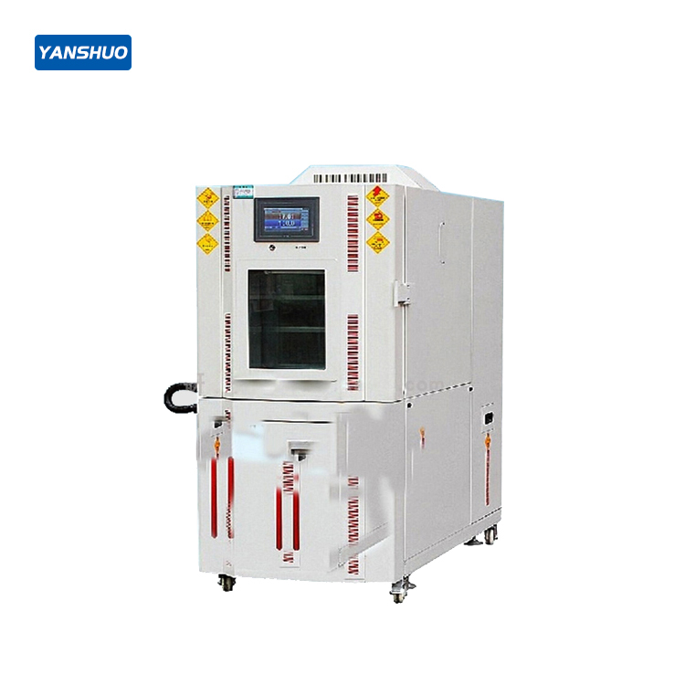
- **YS751‑IV Series Constant Temperature and Humidity Test Chamber (High‑End Export Model)****【Scope of Application】**The constant temperature and humidity test chamber (also known as an environmental testchamber) is used to test the heat resistance, cold resistance,
**YS751‑IV Series Constant Temperature and Humidity Test Chamber (High‑End Export Model)**
**【Scope of Application】**
The constant temperature and humidity test chamber (also known as an environmental test
chamber) is used to test the heat resistance, cold resistance, dry resistance, and humidity
resistance of various materials. It is suitable for quality control in factories producing e
lectronics, electrical appliances, food, vehicles, metals, chemicals, building materials, and other products.
**【Technical Parameters】**
1. **System:** Balanced Temperature & Humidity Control (BTHC) system
2. **Temperature range:** –40°C to +100°C (+150°C as instructed)
3. **Humidity range:** 20% to 98% RH
4. **Temperature accuracy:** ±0.2°C
5. **Humidity accuracy:** ±2.5% RH
6. **Temperature uniformity:** ±0.5°C
7. **Humidity uniformity:** ±3%
8. **Heating time:** –40°C to +100°C — approximately 45 minutes
9. **Cooling time:** +20°C to –40°C — approximately 55 minutes
10. **Inner chamber dimensions (cm):** 50 × 60 × 50
11. **Outer dimensions (cm):** 107 × 147 × 111
12. **Inner chamber material:** Stainless steel, Class 1 mirror‑finish plate
13. **Outer chamber material:** Stainless steel with matte finish
14. **Insulation material:** Rigid polyurethane foam (glass wool for +150°C)
15. **Refrigeration system:** Air‑cooled, single‑stage, fully hermetic compressor
16. **Protection devices:** No‑fuse circuit breaker, compressor overload protection switch,
refrigerant high‑pressure protection switch, over‑temperature protection switch, ceramic fuse,
water tray low‑water protection switch, electromagnetic protection switch, fault warning system, alarm
17. **Accessories:** Observation window, 2 adjustable shelves, 1 test hole (φ50 mm), interior lamp
18. **Weight:** Approximately 250 kg
19. **Power supply:** 3‑phase, AC 220V ±10%, 60 Hz
**【Operating Principle】**
The operation of the constant temperature and humidity chamber relies on the interaction of
three interconnected systems: the refrigerant circulation system, the air circulation system,
and the electrical automatic control system.
1. **Refrigerant circulation system:**
Liquid refrigerant in the evaporator absorbs heat from the air (cooling and dehumidifying the air)
and begins to evaporate, creating a temperature difference between the refrigerant and the air. The
liquid refrigerant completely evaporates into a gas, which is then drawn into the compressor, compressed
(increasing pressure and temperature), and discharged. The gaseous refrigerant releases heat as it condenses
into a liquid while passing through the condenser (air‑cooled or water‑cooled). It then passes through an
expansion valve (or capillary tube), becoming a low‑temperature, low‑pressure liquid before re‑entering
the evaporator, completing the refrigerant cycle.
2. **Air circulation system:**
A fan draws air in from the return air inlet. The air passes through the evaporator (cooling/dehumidifying),
the humidifier, and the electric heater (heating), and is then delivered through the supply air outlet into the
user’s space. The delivered air mixes with the air in the space and returns to the return air inlet.
3. **Electrical automatic control system:**
This includes the power supply section and the automatic control section.
- The power supply section supplies power to the compressor, fan, electric heater, humidifier, etc.,
via contactors.
- The automatic control section consists of temperature/humidity control and fault protection.
- Temperature/humidity control: The controller compares the return air temperature/humidity with the
user‑set values and automatically operates the compressor (cooling/dehumidifying), humidifier, electric
heater (heating), and other components to achieve constant temperature and humidity.
- Fault protection control: Uses pressure protection switches, timers, relays, overload protection, etc.,
to protect the compressor, fan, humidifier, and other components from faults.
**【Instrument Models】**
| Model | Internal Volume (L) | Internal Dimensions H × W × D (cm) |
|----------------|---------------------|-------------------------------------|
| YS751T‑80 | 80 | 50 × 40 × 40 |
| YS751T‑150 | 150 | 60 × 50 × 50 |
| YS751T‑225 | 225 | 75 × 50 × 60 |
| YS751T‑408 | 408 | 85 × 60 × 80 |
| YS751T‑800 | 800 | 100 × 100 × 80 |
| YS751T‑1000 | 1000 | 100 × 100 × 100 |
- **Temperature/humidity control:** Balanced Temperature & Humidity Control (BTHC) system
- **Operating environment:** +5°C to +35°C
- **Heater:** Nickel‑chromium alloy wire heater
- **Humidifier:** Surface evaporation type
- **Fan:** Centrifugal fan
- **Airflow mode:** Broadband forced airflow circulation (upper outlet, lower inlet)
- **Condensation method:** Air‑cooled or water‑cooled
