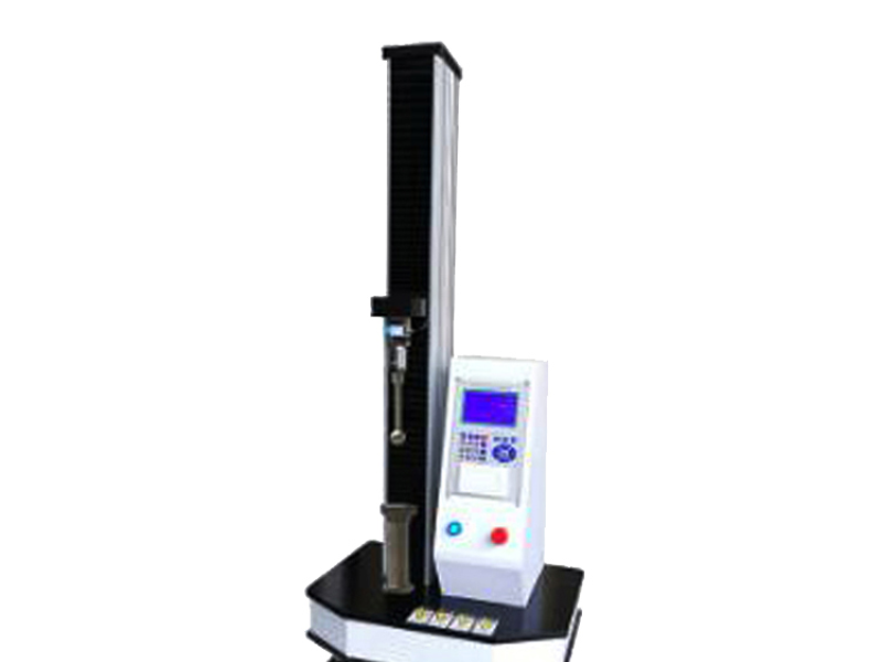
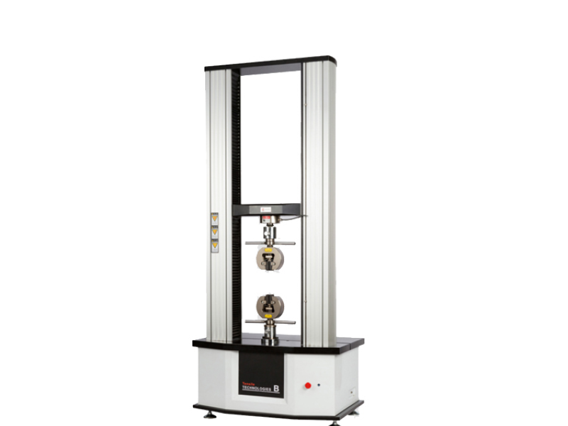
YS-9010B Computer Servo Tensile Testing Machine (Pneumatic Grips)
Scope of Application
【Operating Instructions】
- The computer servo tensile testing machine is widely used for mechanical property testing of rubber, films, FPC, adhesive tapes, nonwovens, cast films, carrier tapes, resins, plastics, metal bars, metal tubes, metal sheets, metal profiles, and composite materials. With appropriate fixtures, it is also suitable for tensile, compression, peel, shear, tear, bending, metal weld strength, and rivet strength tests on various finished products. It can print multiple data items and provide graphical output comparisons based on different data sets, offering high control accuracy and simple operation. The modular design provides a wide variety of accessories with flexible configuration.The computer servo tensile testing machine is mainly used for tensile, compression, bending, and other mechanical property tests on various materials. It can also perform multi‑cycle tests such as constant stress, constant strain, creep, relaxation, axial, and radial tests. According to GB, JIS, ASTM, DIN and other standards, it can automatically determine parameters including tensile strength, yield strength, elongation, stress at given elongation (any percentage), elongation at given stress (any percentage), modulus of elasticity, elongation at break, peel strength (including 90° and 180° peel), flexural modulus, tear strength, adhesion strength, shear strength, etc.
**YS-9010B Computer Servo Tensile Testing Machine (Pneumatic Grips)**
**【Scope of Application】**
The computer servo tensile testing machine is widely used for mechanical property testing of rubber, films,
FPC, adhesive tapes, nonwovens, cast films, carrier tapes, resins, plastics, metal bars, metal tubes, metal sheets,
metal profiles, and composite materials. With appropriate fixtures, it is also suitable for tensile, compression,
peel, shear, tear, bending, metal weld strength, and rivet strength tests on various finished products. It can print
multiple data items and provide graphical output comparisons based on different data sets, offering high control
accuracy and simple operation. The modular design provides a wide variety of accessories with flexible configuration.
The computer servo tensile testing machine is mainly used for tensile, compression, bending, and other mechanical
property tests on various materials. It can also perform multi‑cycle tests such as constant stress, constant strain,
creep, relaxation, axial, and radial tests. According to GB, JIS, ASTM, DIN and other standards, it can automatically
determine parameters including tensile strength, yield strength, elongation, stress at given elongation (any percentage),
elongation at given stress (any percentage), modulus of elasticity, elongation at break, peel strength (including 90° and
180° peel), flexural modulus, tear strength, adhesion strength, shear strength, etc.
**【Applicable Standards】**
GB, JIS, ASTM, DIN, and other standards
**【Instrument Features】**
1. Uses high‑precision full closed‑loop control software for displacement, speed, and load.
2. **Drive:** High‑precision ball screw drive — high efficiency, high rigidity, low deformation, low noise.
3. **Motor:** Japanese Panasonic servo motor drive — provides stable, widely adjustable speed drive
with high speed, low vibration, and high‑speed positioning.
4. **Crosshead material:** Made of 45# die steel, ground — parallelism error ≤ 0.5 mm, high rigidity.
5. **Guidance:** Two‑column guidance using South Korean chrome steel rods — excellent wear
resistance and coaxiality.
6. **Displacement measurement:** Japanese LINE high‑pulse (2500 r/p) photoelectric encoder —
resolution up to 0.001 mm.
7. **Force measurement:** American TRANSCELL precision tension/compression explosion‑proof load cell
— accuracy 0.03% F.S.
8. **Control board:** Self‑developed 32‑bit ARM chip for measurement and control — superior to industry
16‑bit DSP technology, high resolution 1/500,000.
9. **Powerful software:** Suitable for testing different materials and can simultaneously execute different
standards, including international standards (with data processing functions for various standards). Units:
N, kN, g, kgf, lb, cN can be interconverted. The test software, fully designed according to test standards,
is powerful. Test curves can be enlarged, clearly showing the amount, speed, and smoothness of data acquisition,
reflecting the overall processing capability of the hardware and software.
10. **Test reports and curves:** Precise curves, editable test reports, high‑density test curves indicate fast test
sampling frequency — a clear advantage compared to competitors.
**【Technical Parameters】**
Model | YS-9010 | ||
YS-9010B | YS-9010A | ||
Capacity Selection | 5、10、20、30、50、100、200、300、500N 1、2、3、5kN Standard Configuration: One range included as standard; three ranges optional. | ||
Accuracy Class | <1KN:0.1 class ≥1KN:0.25 class | <1KN:0.25 class ≥1KN:0.5 class | |
Force test rang | 0.2%~100%FS(Full Range) | ||
Test Force Meas Range | Model B Indication error within ±0.1%、±0.25%、±0.5% (depending on range) / Model A Indication error within ±0.5% (depending on range) | ||
Test Force Resolution | Model B maximum test force 500000 / Model A maximum test force 200000, No automatic range switching; resolution remains constant across the entire range. | ||
Displacement Parameters Displacement Indication Error : Model B Within ±0.2% of indicated value /Model A Within ±0.5% of indicated value | |||
Displacement Resolution Model B 0.015μm / Model A 0.1μm | |||
Stress Control Speed Range Model B 0.005~5%FS/s / Model A 0.05~5%FS/s | |||
Stress Control Speed Accuracy | Model B: When the speed is < 0.05% FS/s, the tolerance is within ±1% of the set value. When the speed is ≥ 0.05% FS/s, the tolerance is within ±0.5% of the set value. Model A:When the speed is < 0.1% FS/s, the tolerance is within ±2% of the set value. When the speed is ≥ 0.1% FS/s, the tolerance is within ±0.5% of the set value. | ||
Strain Control Speed Range | Model B 0.005~5%FS/s / Model A 0.05~5%FS/s | ||
Strain Control Speed Accuracy | Model B When speed < 0.05% FS/s: within ±1% of set value When speed ≥ 0.05% FS/s: within ±0.5% of set value Model A When speed < 0.1% FS/s: within ±2% of set value - When speed ≥ 0.1% FS/s: within ±0.5% of set value | ||
Displacement Contl Speed Range | Displacement Control Speed Range Model B0.001~500mm/min / Model A0.01~500mm/min | ||
Displacement Control Speed Accuracy |
Model B: Within ±0.2% of the set value Model A: Within ±0.5% of the set value | ||
Force Control Speed Relative Error | Model B: Within ±1% of the set value Model A: Within ±2% of the set value | ||
Constant Stress, Constant Strain, Constant Displacement Control Range Model B 0.5%~100%FS / Model A 1%~100%FS | |||
Constant Stress, Constant Strain, Constant Displacement Control Accuracy Model B: When the set value is ≥ 10% FS: within ±1% of the set value When the set value is < 10% FS: within ±0.1% of the set value Model A: When the set value is ≥ 10% FS: within ±2% of the set value When the set value is < 10% FS: within ±0.5% of the set value | |||
Size | Dimensions (L × W × H) 500×600×1500mm/1650mm | ||
Test Space without Fixtures: 850/1200mm Or Customized | |||
Fixture Center to Column (distance) 70mm(Or Customized ) | |||
power input | 220V 50Hz,±10% | ||
power | 0.4KW | ||
weight | 95KG | ||


