YS-CS-2 Bunched Wires and Cables Combustion Tester
Scope of Application
【Operating Instructions】
- This bunched wires and cables combustion tester is strictly manufactured in accordance with GB/T 18380.31-2008 and equivalently adopts the IEC 60332-3-10:2000 standard. It is used to evaluate the ability of vertically installed bunched wires, cables, or optical cables to resist the vertical spread of flame under specified conditions. It is an economical and practical device widely used in the wire and cable industry.
YS-CS-2 Bunched Wires and Cables Combustion Tester
Applicable Scope:
This bunched wires and cables combustion tester is strictly manufactured in accordance with GB/T 18380.31-2008 and equivalently adopts the IEC 60332-3-10:2000 standard. It is used to evaluate the ability of vertically installed bunched wires, cables, or optical cables to resist the vertical spread of flame under specified conditions. It is an economical and practical device widely used in the wire and cable industry.
Compliance Standards:
GB/T 18380.31-2008, IEC 60332-3-10:2000
Instrument Features:
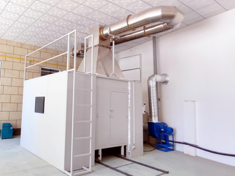
The test apparatus is a self-standing chamber measuring 2500 mm in length, 3200 mm in width, and 4500 mm in height, with its base elevated above the ground. The chamber is sealed around its perimeter. Air flows into the chamber through an 800 mm × 400 mm air inlet located at the bottom, 150 mm from the front wall. A 300 mm × 1000 mm exhaust outlet is located at the rear top of the chamber. The rear wall and both sides of the chamber use thermal insulation with a heat transfer coefficient of approximately 0.7 W·m⁻²·K⁻¹. The distance between the steel ladder and the rear wall of the chamber is 150 mm. The lowest rung of the steel ladder is 400 mm from the ground, and the lowest point of the cable specimen is approximately 100 mm from the ground.
Technical Parameters:
1. Combustion Chamber Section:
Overall Dimensions: 2500 mm (L) × 3200 mm (W) × 4500 mm (H)
Material: Thermal insulation with a heat transfer coefficient of 0.7 W·m⁻²·K⁻¹, consisting of stainless steel plates covered with 65 mm thick mineral fiber.
Air Source: Controls the gas flow rate through the chamber to (5000 ± 500) L/min, maintaining a stable airflow during the test. Includes a spraying device to forcibly stop combustion after the test.
Steel Ladder Type: Standard width 500 mm steel ladder / Wide 800 mm steel ladder.
Emission Purification Device: Equipped with a smoke collection and scrubbing device that does not alter the airflow rate through the chamber.
Ignition Source: Includes one or two ribbon-type propane gas burners with matching flow meters and Venturi mixers. The fire supply surface is a flat metal plate drilled with 242 holes of 1.32 mm diameter. The centers of these holes are 3.2 mm apart, arranged in three staggered rows of 81, 80, and 81 holes respectively, distributed within a nominal area of 257 × 4.5 mm. Additionally, a row of small guide holes is drilled on each side of the burner plate to maintain stable flame combustion.
a. Each burner is equipped with a rotor flow meter to accurately control the inflow rate of propane and air.
b. Under reference conditions of 100 kPa and 20℃, the test gas flow rates are: Air (77.7 ± 4.8) L/min; Propane (13.5 ± 0.5) L/min.Ignition Source Position: The burner is placed horizontally, (75 ± 5) mm from the front surface of the cable specimen, (600 ± 5) mm from the bottom of the chamber, and symmetrical to the axis of the steel ladder. The burner's fire supply point should be located at the center between two rungs of the steel ladder and at least 500 mm from the lower end of the specimen.
Observation Window: One tempered glass observation window, edged with stainless steel.
Exhaust System: 2 spiral exhaust fans; sealed sliding plates made of 2.0 mm stainless steel.
Air Inlet: 1 (φ160 mm).
Bottom Fixing Frame: Made of 40 mm × 40 mm square tubing.
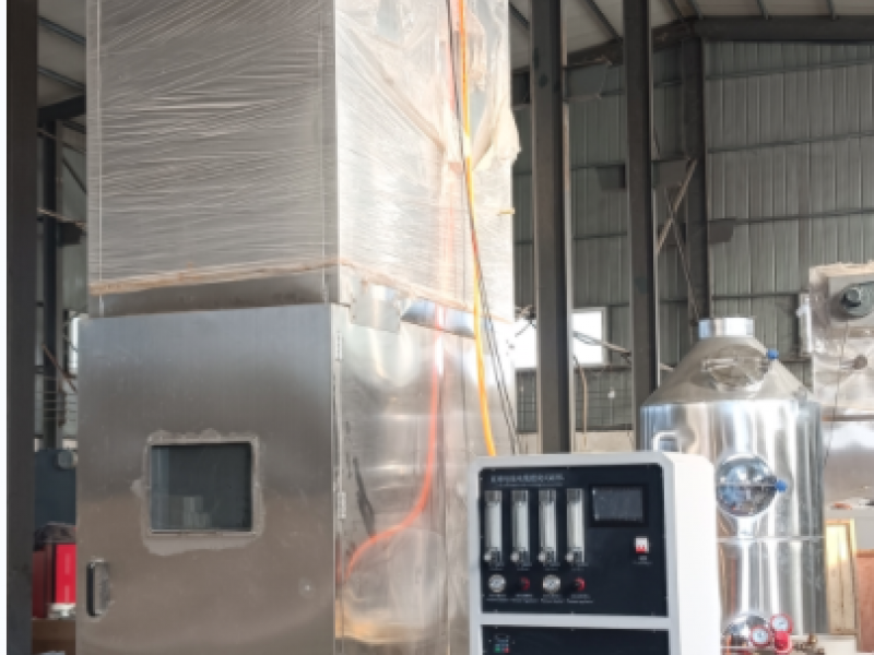
2. Control Section:
Air Flow Adjustment: Adjusts the test air flow rate to approx. 77.7 L/min under reference conditions of 100 kPa and 20℃.
Gas Flow Adjustment: Adjusts the test gas flow rate to approx. 13.5 L/min under reference conditions of 100 kPa and 20℃.
Air Pressure Display: Displays the test air pressure.
Gas Pressure Display: Displays the test gas pressure.
Air Pressure Regulation: Adjusts the intake air pressure.
Gas Pressure Regulation: Adjusts the intake gas pressure.
Temperature Display: Monitors and displays the test temperature.
Chamber Internal Temperature Display: Displays the internal temperature of the combustion chamber.
Combustion Time: Set the combustion time applied to the specimen according to standard requirements. When the instrument starts ignition, timing begins immediately. Upon reaching the set time, it automatically switches to the afterflame timer, which runs automatically. Can be set arbitrarily from 0 to 99.99 S/M/H.
Afterflame Time: Once the combustion time is reached, the afterflame timer starts running until the specimen flame extinguishes naturally, no droplets fall, or all objects are free of open flames. Pressing the "Afterflame Pause" key freezes the time on the display, which is recorded as the afterflame time.
Afterflame Pause: Pressing "Afterflame Pause" freezes the timer at the current instantaneous time.
Ignition: After setting the combustion time according to standard requirements, press the "Ignition" key. The igniter lights up, igniting the burner, and the flame is applied to the specimen to start combustion.
Stop: Pressing the "Stop" key stops the burner flame and resets all timers.
Power: Power supply is AC 220V 50Hz. Connect the power cord, turn on the power switch, and the instrument starts.
Circulating Water Pump: Pressing the "Circulating Water Pump" key starts the water pump, and the water tower performs waste gas filtration.
Fan: The exhaust fan operates.
Single/Double Burner: Selects between single and double burner modes.
3. Test Section:
Combustion Chamber: 2000 mm (L) × 1000 mm (W) × 4000 mm (H)
Ribbon-type Propane Gas Burners: 2 units
Steel Ladders: Standard 500 mm width steel ladder, Wide 800 mm width steel ladder
370W Single-phase Water Pump: 1 unit
Inner Flame Contact Point Ruler: 1 unit
Paper Size Ruler: 1 unit
Test Length Ruler: 1 unit
Test Fixing Frame: Material: Steel plate finely processed and painted, pure black.
Precautions:
Before the test, connect the liquefied petroleum gas tank hose with the pressure regulating valve first, then connect the signal control wires and turn on the power switch of the control box. Check that the connections are correct and ensure there are no gas leaks. If there are no leaks, the power switch can be turned to the "ON" position. Open the main valve of the gas cylinder and turn on the pressure regulating valve. The high-pressure gauge of the acetylene (pressure reducing valve) should indicate a pressure between 0.01 and 0.02 MPa (this is the working pressure). Exceeding 0.02 MPa is dangerous and may indicate a gas leak.
After the test, turn off the power switch and the main valve of the gas cylinder. Do not leave the site until it is confirmed that there are no burning materials or sparks.
Test Method:
Specimen Selection:
a. The specimen shall consist of several equal-length cable specimen sections. The minimum length of each cable specimen section is 3.5 m.
b. The total number of cable specimen sections should be such that the volume of non-metallic material contained in the total volume...
c. Specimens should be selected within the range specified in Table (1).
d. Before the test, the cable specimen sections should be conditioned at (20 ± 10)℃ for at least 16 hours. The cable specimen sections should be dry.Determination of the Number of Cable Specimen Sections:
a. To calculate the number of cable specimen sections, the volume of non-metallic material per meter contained in one cable specimen section should be determined.
b. Carefully cut a cable section of not less than 0.3 m. Its cross-section should be perpendicular to the cable axis to allow for precise length measurement.
c. The density of each non-metallic material (including foamed materials) should be measured using an appropriate method, with data rounded to the second decimal place.
d. Peel off each non-metallic material Ci from the cable section and weigh it. Any material accounting for less than 5% of the total mass of non-metallic materials should be assumed to have a density of 1 kg/dm³.
e. If the semi-conductive shield cannot be peeled off from the insulating material, they can be measured together for mass and density.
The volume Vi (L/m of cable) of each non-metallic material Ci is calculated by the following formula:
(Note: The original text omitted the formula)
Where:
Mi — Mass of material Ci, in kilograms (kg);
pi — Density of material Ci, in kilograms per cubic decimeter (kg/dm³);
l — Length of the cable specimen section, in meters (m).
The total volume V of non-metallic material per meter of cable is equal to the sum of the volumes V1, V2, etc., of the various non-metallic materials.
Divide the volume per meter specified in the test standard by the total volume V of non-metallic material per meter of cable to obtain the number of cable specimen sections to be installed. Round to the nearest integer (round up 0.5 to 1) and install them on the steel ladder.Specimen Installation:
Some cables with a cross-section exceeding 35 mm²:
For cables with at least one conductor cross-section exceeding 35 mm², each cable specimen section should be fixed to each rung of the steel ladder using metal wire (steel or copper wire). Cables with a diameter of 50 mm and below use metal wire with a diameter of 0.5 mm to 1.0 mm. Cables with a diameter above 50 mm use metal wire with a diameter of 1.0 mm to 1.5 mm.
The cable specimen sections should be installed in a single layer on the front of the steel ladder. The spacing between cable specimen sections should be 0.5 times the cable diameter, but not exceeding 20 mm. Regardless of whether a standard or wide steel ladder is used, the minimum distance between the edge of the specimen and the inner vertical surface of the steel ladder should be 50 mm.
The maximum width of the specimen on the standard steel ladder should be 300 mm. The maximum width on the wide steel ladder should be 600 mm.
When installing cable specimen sections, the first section should be positioned roughly at the center of the steel ladder. Subsequent sections are added on both sides so that all sections are arranged roughly in the center of the ladder.
For AF/R class cables, a standard double-layer spaced installation is used. Please refer to (Table 1) for specific operations.
During installation, each cable specimen section should be fixed to each rung of the steel ladder using metal wire (steel or copper wire). Cables with a diameter of 50 mm and below use metal wire with a diameter of 0.5 mm to 1.0 mm. Cables with a diameter above 50 mm use metal wire with a diameter of 1.0 mm to 1.5 mm.
When using a standard steel ladder, the specimen should include at least 4 cable specimen sections. At least two sections should be installed on the back of the steel ladder.
When more than 4 cable specimen sections are needed, subsequently installed sections should be alternately installed on the front and back of the steel ladder.
The entire specimen should be installed as follows:
— The spacing between cable specimen sections in one layer (front or back) should be 0.5 times the cable diameter, but not exceeding 20 mm;
— The maximum width of a single layer should be 300 mm;
— The minimum distance between the specimen edge and the inner vertical surface of the steel ladder should be 50 mm;
— Cable specimen sections installed on the back of the steel ladder should be located at the center of the gaps between the specimen sections on the front;
— All cable specimen sections should be arranged roughly in the center of the steel ladder.Some cables with a cross-section of 35 mm² and below:
For cables with conductor cross-sections not exceeding 35 mm², the cable specimen sections should be fixed to each rung of the steel ladder individually or in groups using metal wire (steel or copper wire) with a diameter of 0.5 mm to 1.0 mm.
The cable specimen sections should be installed in one or more layers in contact with each other on the front of the standard steel ladder. The maximum width of the specimen should be 300 mm. The minimum distance between the specimen edge and the inner vertical surface of the steel ladder should be 50 mm.
When installing cable specimen sections, the first section (or group) should be positioned roughly at the center of the steel ladder. Subsequent sections (or groups) are added on both sides so that all sections are arranged roughly in the center of the ladder.
If the first (or subsequent) layer uses the full width of the steel ladder and a second (or more) layer is needed, the first section (or group) of the second (or subsequent) layer should be positioned roughly at the center of the steel ladder. Subsequent sections (or groups) are added on both sides so that all sections of the second (or subsequent) layer are arranged roughly in the center of the ladder.
If a large number of cable specimen sections are needed, flat groups of cable specimen sections can be formed using the specified metal wire and installed on the steel ladder rungs. The maximum width of each cable specimen section group is 5 sections. To ensure consistency, it is recommended to fix adjacent cable specimen section groups tightly together on each rung to ensure the sections are in contact with each other.
(Standard steel ladder single-layer contact installation)Fire Supply Time:
The fire supply time for AR/F, A, and B class cables is 40 minutes; for C and D class cables, it is 20 minutes. After this, the flame should be extinguished. The airflow through the test chamber should be maintained until the cable stops burning or glowing, or for a maximum of 1 hour, after which the cable's burning or glowing should be forcibly extinguished.Evaluation of Test Results:
After the cable burning or glowing stops or is extinguished, the specimen should be wiped clean. After cleaning, if the original surface is not damaged, all soot can be ignored. Softening of non-metallic materials or any deformation is also ignored. Flame spread should be determined by the extent of damage. The extent of damage is the distance from the bottom edge of the burner to the starting point of the charred part, in meters, accurate to 2 decimal places. The starting point of the charred part is determined as follows:
Press a sharp object, such as a knife edge, against the cable surface. The point where the surface changes from elastic to brittle (powdery) indicates the starting point of the charred part.Performance Requirements:
Performance requirements for specific models or types of wires and cables should be specified separately in the relevant cable product standards. When no performance requirements are given, the maximum charred range of the specimen measured, whether on the front or back of the steel ladder, should not be higher than 2.5 m above the bottom edge of the burner.Retest Procedure:
If the specimen fails this test and there is a dispute, two more tests should be conducted according to the above provisions. If the results of both tests meet the stated requirements, the wire and cable should be considered to have passed this test.Test Report:
The test report should include the following information:
i. Complete description of the tested cable;
j. Manufacturer of the tested cable;
k. The part of the standard referenced for conducting the test.
Installation Requirements:
Space Requirements:
External Dimensions: Overall space dimensions: Width 2500 mm, Depth 4500 mm, Height 5500 mm.
Weight: Approx. 205 tons (Note: The original text states 205 tons, which seems unusually heavy for this equipment; please verify if this should be 2.05 tons or 2050 kg).
Test Bench: Length not less than 6 m, Height × Width: 5 m × 5 m.
Power Requirements:
Voltage: 220V ± 10%, 50Hz.
Power: 7 kW.
Water Source: Cooling water source with matching sewage discharge.
Gas Source: Industrial propane / 3 kW air compressor with a flow rate of not less than 300 L/min.
Pollutant Description: Smoke and dust.
Ventilation Requirements: Smoke collection should be connected to a smoke treatment and purification system.
Other Test Requirements: Gas cylinders with matching pressure reducing valves. Due to the large size of the equipment, a forklift of over 5 tons is required for unloading. A crane is needed for hoisting, and three sets of scaffolding approximately 5 meters high are also required.
Flame Retardant Series of Cables & Building Materials
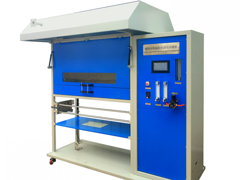
YS-JC-2 Radiant Heat Flux Test Apparatus for Flooring Materials
Flame Retardant Series of Cables & Building Materials
YS-JC-1 Single Burning Item (SBI) Test Apparatus for Building Materials and Products

